Coating Thickness Uniformaty를 향상시키기위한 조건
고품질 스핀코팅막을 얻기위한 테크닉
Photoresist for defining patterns in microcircuit fabrication on wafer.
Dielectric/insulating layers for microcircuit fabrication ? polymers, SOG,
SiLK, etc.
Magnetic disk coatings - magnetic particle suspensions, head lubricants,
etc.
Flat screen display coatings. - Antireflection coatings, conductive oxide, etc.
Compact Disks ? DVD, CD ROM, etc.
Television tube phosphor and antireflection coatings.
--------------------------------------------------------------------------------
스핀코팅 Quality 결정단계
APT Gernan의 Spincoater는 축적된 다년간의Know-how를 바탕으로 최고의 성능을 발휘하도록 설계되었습니다
스핀코팅 프로세스는 4단계로 나눌수 있습니다.
스테이지 3 (flow controlled) 과 스테이지
4 (evaporation controlled) 가 마지막 코팅두께의 유니포머티에
가장 중요한 단계라 핳수 있습니다.
--------------------------------------------------------------------------------
스테이지 1: The first stage is the
deposition of the coating fluid onto the wafer or substrate.
It can be done
using a nozzle that pours the coating solution out, or it could be sprayed onto
the surface, etc.
Usually this dispense stage provides a substantial excess of
coating solution compared to the amount that will ultimately be required in the
final coating thickness.
For many solutions it is often beneficial to dispense
through a sub micron sized filter to eliminate particles that could lead to
flaws.
Another potentially important issue is whether the solution wets the
surface completely during this dispense stage. If not, then incomplete coverage
can result.
--------------------------------------------------------------------------------
스테이지 2: The second stage is when the
substrate is accelerated up to its final, desired, rotation speed.
This
stage is usually characterized by aggressive fluid expulsion from the wafer
surface by the rotational motion.
Because of the initial depth of fluid on the
wafer surface, spiral vortices may briefly be present during this stage; these
would form as a result of the twisting motion caused by the inertia that the top
of the fluid layer exerts while the wafer below rotates faster and faster.
Eventually, the fluid is thin enough to be completely co-rotating with the wafer
and any evidence of fluid thickness differences is gone.
Ultimately, the wafer
reaches its desired speed and the fluid is thin enough that the viscous shear
drag exactly balances the rotational accelerations. 
--------------------------------------------------------------------------------
스테이지 3: The third stage is when the
substrate is spinning at a constant rate and fluid viscous forces dominate fluid
thinning behavior.
This stage is characterized by gradual fluid thinning.
Fluid thinning is generally quite uniform, though with solutions containing
volatile solvents, it is often possible to see interference colors "spinning
off", and doing so progressively more slowly as the coating thickness is
reduced.
Edge effects are often seen because the fluid flows uniformly outward,
but must form droplets at the edge to be flung off.
Thus, depending on the
surface tension, viscosity, rotation rate, etc., there may be a small bead of
coating thickness difference around the rim of the final wafer.
Mathematical
treatments of the flow behavior show that if the liquid exhibits Newtonian
viscosity (i.e. is linear) and if the fluid thickness is initially uniform
across the wafer (albeit rather thick), then the fluid thickness profile at any
following time will also be uniform --- leading to a uniform final coating
(under ideal circumstances). 
--------------------------------------------------------------------------------
스테이지 4: The fourth stage is when the
substrate is spinning at a constant rate and solvent evaporation dominates the
coating thinning behavior.
As the prior stage advances, the fluid thickness
reaches a point where the viscosity effects yield only rather minor net fluid
flow.
At this point, the evaporation of any volatile solvent species will become
the dominant process occurring in the coating. In fact, at this point the
coating effectively "gels" because as these solvents are removed the viscosity
of the remaining solution will likely rise -- effectively freezing the coating
in place. (This behavior was used in the seminal work of Meyerhofer (J. Appl.
Phys. 49 (1978) 3993) where he quantified the coating thickness dependence on
spin speed and viscosity and its relationship to the evaporation rate.)
After spinning is stopped many applications require that heat treatment or "firing" of the coating be performed (as for "spin-on-glass" or sol-gel coatings). On the other hand, photoresists usually undergo other processes, depending on the desired application/use.
Clearly stages 3 and 4 describe two processes that must be occurring
simultaneously throughout all times (viscous flow and evaporation). However, at
an engineering level the viscous flow effects dominate early on while the
evaporation processes dominate later. 
--------------------------------------------------------------------------------
Fluid Flow
Complications
The flow behavior described above ignores several
effects that are important for many coating solutions.
As noted above, the
evaporation step is critical in defining what the final coating thickness will
be. But, evaporation occur -- by necessity -- from the top surface, and only
some of the solution components are volatile enough to evaporate to any
substantial degree.
Thus, there will necessarily be an enrichment of the
non-volatile components in the surface layer of the coating solution during the
spinning process. The figure at right illustrates that concept.
One of the key
consequences is that this surface layer will very likely have a higher viscosity
than the unmodified starting solution (this may simply be due to the higher
concentration, but might also occur because of cross-linking effects, etc).
With
a higher viscosity, it will then impede the flow characteristics set out above,
making it a difficult differential equation to solve directly. And, this surface
layer may have the secondary result of reducing the evaporation rate. So both
the evaporation and flow processes are coupled through the behavior of the
"skin" that develops on the top of the outwardly flowing solution during spin
coating.
Another important effect is that some solutions are not "Newtonian"
in their viscosity/shear-rate relationships. Some solutions change viscosity
depending on what shear rate is used, thus depending on distance from the
center, the shear rate will be different and thus the flow behavior.
This can
give radial thickness variation that varies rather smoothly in a radial sense,
as pointed out by Britten and Thomas [J. Appl. Phys. 71 (1992) 972-979].
Air Flow Effects Important for Spin Coating
Air Flow Basics (Ideal Case)
The image at the right, from Millsaps and
Pohlhausen, [J. Aeronautical Sci., (1952) 120-126] shows a schematic of the
ideal airflow field above an infinitely large spinning disk. At the surface of
the disk there is a "no-slip" condition so the contacting air must be exactly
co-rotating --- hence the flow vectors pointing essentially tangentially to any
point at a given radius (and proportional to the distance from the center).
At
moderate distances from the surface a centripetal acceleration must be provided
by the viscous effects; this condition is thus maintained only when some outward
radial air flow is also occurring. This outward flow is balanced by some minor
downdraft over the entire wafer.
This is a steady state configuration and does
not include inertial effects included in the "spin-up" stages. This air flow
pattern also only hold true so long as the flow is laminar. A "boundary layer"
of uniform thickness thus exists over the entire surface area of the spinning
wafer: it is through this boundary layer that evaporating solvent must diffuse.
Because the boundary layer is constant in thickness over the wafer then the
evaporation rate as a function of position is predicted to also be constant. 
--------------------------------------------------------------------------------
Air Flow Complications
The steady flow field described above is limited
to cases where the flow is laminar and where it is "steady". In fact, except for
very large wafers, most spinning conditions DO satisfy the constraint of having
laminar flow.
However, there can be un-steady oscillating instabilities in the
boundary layer near the surface of the wafer. These form spiral shaped waves or
rolls that are called "Ekman" spirals. Wahal, et al [Applied Physics Letters 62
(1993) 2584-6] have experimentally observed Ekman spirals (shown in the figure
at right) for nominally laminar conditions in spin coating.
They claim that
these instabilities can lead to coating thickness variations, but have not
explained WHY that would be the case.
APT Spincoater의 특장점
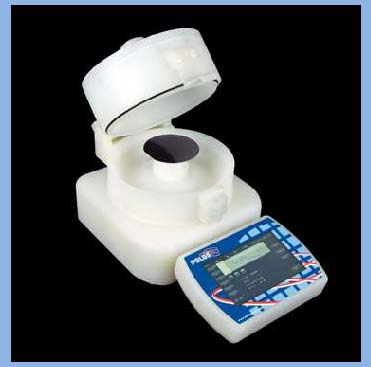 APT SPIN150i APT SPIN150i |
|
|
|
||
 |
||
 |
재성ITS co.
경기도 안양시 동안구
호계555-9
안양
국제 유통스텝지 17동
127호
Tel
: (031) 479-4211/2, Fa* : (031) 479-4213
1992-2014
,Jsi.co. All rights reserved
Contact us : jsi@jsits.com
스핀코터/Spincoater 스핀코터/Spincoater 스핀코터/Spincoater 스핀코터/Spincoater 스핀코터/Spincoater 스핀코터/Spincoater 스핀코터/Spincoater